Minimalistic HIFI Bi-Amplified Speaker System
30 Jan 2014
There are numerous advantages to self-powered bi-amped speakers, including more efficient and quality cross-overs, amplifier-to-driver matching, driver response equalization, and lower distortion. These benefits, however, come at the cost of making these systems complex - a professional studio monitor has 10+ amps, split among the filter sections, protection circuitry, gain stages, etc. These in turn require at least low voltage and high voltage power supplies, leading to a complex design that is hard to build as DIY, more prone to failure, has higher distortion and noise, etc.
Here I present a system of my own design with minimal number of components, yet delivering all benefits listed above. It is based on the popular in studio monitors 4th order (24 dB/octave) Linkwitz-Riley cross-over since it allows for phase aligning the tweeter and woofer at the cross over-frequency. The novelty here is in adding significant filter gain in the pass-band region, which allows us to use the power amplifier as the active element of the active cross-over. This eliminates the need for any opamps and extra voltage supplies. The resulting filter is imperfect (in fact each channel has many poles and zeros), but due to the strength of the power amplifier (compared to an opamp) a wider range of resistor values can be chosen to qualitatively eliminate the imperfection. The frequency response is further shaped by frequency dependent impedence in the feedback loop to boost the bass and cut the supersonic frequency content.
Here is the complete circuit diagram:

A Bi-Amp system with just one active element - a stereo power amplifier IC.
The schematic is concise because components play multiple functions. The block diagram should clarify what is happening.
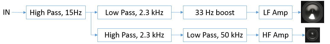
Block diagram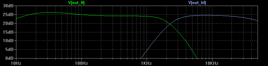
Bode plot
The system is a constant summed voltage bi-amplifier around the cross-over frequency. Furthermore, at 2.3 kHz the tweeter channel is delayed by 70 degrees relative to the bass channel, which transaltes to 3 cm in air, to account for the typical in speakers mounting of both the shallow tweeter and the deep woofer on the same plane (remember that at high frequencies, woofers produce sound from the middle, near the voice coil).
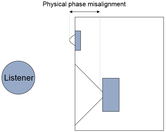
The physical misalignment must be corrected electronically.
The optional bass booster adds a 2 dB power gain around 33 Hz for use in speakers with small woofers and ports tuned low.
I implemented the amplifier on a 2-layer board with 0805 SMD components. My design goal was to keep dimensions small and traces short. The power section (rectifier + speaker supply) and the filters use separate ground planes to prevent ground loops.
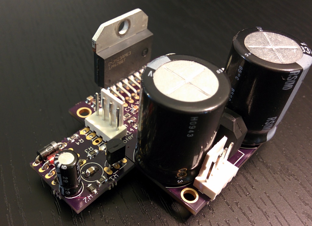
Construction
I hand-soldered the components onto the PCB and mounted the IC to an old CPU heatsink.
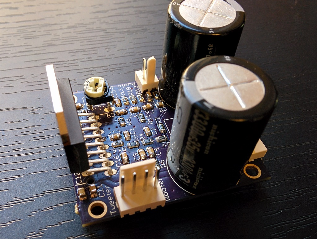
The finished board.
I removed the poor stock cross-over from my modded Boston Acoustics CS26 and mounted my board inside, hooked up to a 18-0-18V toroid transformer (link) for ±25V supply. For safety I added one 2A fuse in series with the primary AC winding, and another one in series with the tweeter. There is no capacitor in series with the tweeter since the circuit produces practically no turn-on pop. To minimize piezoelectric effects on the capacitors (from acoustic pressure), I covered the filter capacitors with hot glue.
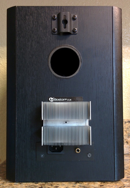
The heatsink is outside for better cooling.
Listening Tests
The completed speaker is a noticeable improvement over the already good stock CS26 hooked to a quality amplifier. The notch around 3 kHz is gone, and the phase aligning of the 2 drivers makes sound more "present" - now it better produces the sense of a musical instrument behind the speaker. The tweaked bass reflex port combined with the minor bass boost improves the bass audibly, though not quite chest pounding as my 10" Bose 501s.

Room frequency response of my speaker and the Behringer B3031A.
I have since tweaked the filter to remove the 2.2 kHz peak, but have not remeasured. The 4.2 kHz peak remains and is due to tweeter internal resonance.
8 seconds of Pink Martini's "The Gardens Of Sampson & Beasley".
Original, followed by a microphone recording as reproduced by my speaker, then original again, then the B3031A.
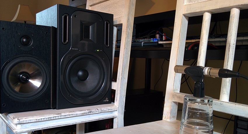
Measurement setup.
Update
I added clipping detection in this post.

Comments for Minimalistic HIFI Bi-Amplified Speaker System
Shane on February 22, 2014
This is AWESOME! I have a question though. Is this schematic pretty universal? For instance, I have event 20/20 monitors, the old model not the new powered ones. Right now as they are, I have to use a separate power amp. Furthermore, one of the circiut boards got fried, so the tweeter on the left one doesn't even work. So my question is, could I use this exact schematic, parts and all, to not only make my mons powered, and fix the tweeter issue? I know that I would have to add the power input, but that would just be wired directly to the bi-amp board you provided right? Email would be the best way to contact me, if you need it ask, I'm not sure if you'll see it or not since it says hidden next to it haha.
Rouslan on February 26, 2014
Thanks!
It should work as is. Your speakers have the cross-over set at 2.3kHz which exactly coincides with my design. Use the potentiometer to adjust the levels to match your speaker sensitivities.
Finally, for protection, use light bulbs or resistors (20-50 ohm) in series with both drivers for the initial test.
Good luck!
jc on March 15, 2014
Hi, I'd like to use this amp crossed around 4000 Hz by replacing R3 with a 8.2K and R10 with a 39K. Could this work ?
Rouslan on March 23, 2014
You'll need to change all of R2-R5 and R9-R12.
As a reasonable approximation, consider the 4th order LR filters above to be made of two 2nd order Sallen-Key filters. Then go to http://sim.okawa-denshi.jp/en/OPseikiLowkeisan.htm and play with the second calculator (ie where you enter Fc, C1 and C2).
Michael on March 23, 2014
Hey, Thanks for sharing the Pink Martini. I've got to find more stuff from them!
djb on March 31, 2014
Hey. Very nice project. I followed this one and i notice that you recently add R16 and C17 . What is the purpose ? I have a secondquestion, may i add a potentiometer in serie with R6 and one in serie R13 to control the gain of the low and high frequncy amps ?
glen on April 2, 2014
what software do you use to do the spectrum mersuerments
Rouslan on April 6, 2014
djb -
R16 and C17 bias the differential input stage of the amplifier to remove DC offset. Alternatively, you can add a capacitor in series with R6, but the latter approach has higher distortion.
glen -
I used RightMark Audio Analyzer for measuring, LTSpice for simulation.
Rouslan on April 8, 2014
I added a protector circuit - at 40W for the woofer and 20W for the tweeter, the amp is muted for 1 second.
djb on April 12, 2014
Is It a crowbar circuit ? Can you up the shematic ?
djb on May 22, 2014
Hello, i would like to add a potentiometre as a preamp, do you have any recomandation about the value of this one in order to keep a good sound quality ? Would you recommand an active or a passive preamp ?
Rouslan on June 7, 2014
I recommend making the preamp active. The current circuit has frequency dependent input impedance and thus adding a potentiometer will work only if it has low resistance (<1 kOhm). A 10-50 kOhm potentiometer would be better. Figuring out the protector can be fun, so I let you give it a try. It is not a crowbar.
Asim on July 13, 2014
Sir please tell me that how much AC i need to supply to it..?? Please tell me i have built it to use but i don't know how much voltage is needed to supply at 12v AC it doesn't work i can try increasing the voltage but it would be fabulous if you tell me the exact amount it requires.
djb on August 5, 2014
Asim, not sure if i understand your question but i ll try to answer. The typical AC voltage needed for an output power of 25W into a 8hom load is 2*18Vac . In fact this double Ac voltage will give you a symetric DC suply of ±25 Vdc Now if you want to use a double 12 Vac supply it should work but you will have a ±15 Vdc supply which will give you a maximum power of 10W (according to the datasheet.) Maybe your problem is that you are using a none double 12Vac supply... In this case you are not getting a symetrical VDC.